


Posted on 1/23/24 11:49 AM
Cable is a sleek composite of resins and metals which are vital materials of making world-class power cords and cord sets. While dependable and durable, even essential to modern-day life, cable is also susceptible to acute bending, especially near the point where the cord exits the equipment. Underneath the smooth resinous skin of our example cord, lay three conductors of extruded copper wire. If those wires are extremely bent or otherwise damaged, the result could be loss of electrical continuity or shortened lifespan—protecting your cord’s bend radius helps maintain connectivity. And understanding your cord’s recommended minimum bend radius for cable is critical to the maintenance and longevity of the cable and the machines and equipment powering them.
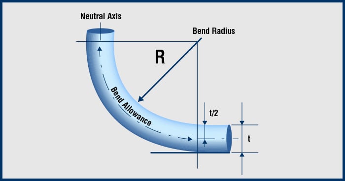
Calculating Bend Radius
Calculating how far a cable can bend without causing material damage depends on the jacket material and the flexibility of the wires and insulators inside—and the diameter of the cable. The outer diameter of the cable times the cable multiplier equals the minimum bend radius. Cable multipliers vary according to the type of cable and applicable industry standards.
What is the recommended minimum bend radius for cable? The National Electrical Code Handbook (NEC) and HD 516 lists minimum bend radius requirements. Interpower Technical Support Specialist, Dan Ford on bend radius:
“It depends on the size of cable and the material,” Ford said. “Some cables bend easier than others, their jacket materials offering varying degrees of flexibility. Fillers or shielding inside the cable will decrease its ability to bend.” Ford added that finer strands of wire allow for more flexibility than larger strands—the hardness or elasticity of the material affects the severity of its bend.
If cable repeatedly exceeds the minimum bend radius, issues may include cracked insulation, broken conductors, or splits in the jacket or conductor wires. For example, if the jacket material is a harder material, it may not survive an “8” radius, but possibly a “12.” The harder or more rigid the material, the more prone it is to damage.
“The 8 and 12 are multipliers used with cable diameter to determine the bend radius. The units of cable diameter are measured in either millimeters or inches. Other factors such as application, movement, temperature, and material hardness can affect the amount of safe radius bend. Cable manufacturers need to combine all factors of radius bend when making a final recommendation.”
Ford compared the bend radius of a cable to that of a garden hose which is bent to the point where it kinks, blocking the flow of water. In the same way a cable can be bent to where it can no longer transmit the flow of electrons.
“Bend radius failures usually occur over time,” Ford said. “It is important to avoid excessive bending of the cable which can shorten its life, potentially leading to shock, or arcing and pitting which could lead to fire,” Ford said. “How the end user treats the cable plays a big role in what the actual bend radius will be. For example, if the cord is plugged into the wall and then jerked from side to side for removal, that will violate the bend radius. If the cord is repeatedly twisted, that will affect it as well.”
Indicators of Bend Radius Failures:
- Discoloration of the cable
- Wrinkling, pinching, or kinking of the cable
- Stress tears on the cable jacket
- Increased resistance of the cable with the meter (a high resistance rating can indicate damage)
 Strain Reliefs
The main purpose of a strain relief or cable gland is to provide protection to a power cord. They help extend cord life and add stability to the equipment. In generic terms, it is used to secure a power supply cord to a machine or an electrical device. The term strain relief is commonly used in North America, while cable gland is the preferred European term.
Thread Types
Different types of mounting threads are available: National Pipe Thread (NPT) is the American standard and is most commonly used in the United States; Stahlpanzerrohr-Gewinde, also called Panzergewinde (PG), is the German military thread used in Germany and Europe; the metric type which originated in Europe is used worldwide.
Location is a major factor in determining type. If located in North America, NPT or metric threads should be chosen. In Europe, metric is often used for new equipment while PG is used for replacement parts. While all thread types secure fittings to equipment, minor differences include the thread spacing and tapering in each type. Using the wrong type for your application may result in an improper fitting or connection resulting in cross-threading.
| American Standard | Germany/Europe | Worldwide |
|---|---|---|
|
National Pipe Thread (NPT) Tapered and Self-locking
|
Stahlpanzerrohr-Gewinde/Panzergewinde (PG)
|
Metric
|


Cable and Wire Size
Cable diameter determines the size of the strain relief. The outer diameter of the cable must be known in order to select the appropriate strain relief which will be listed in specification guidelines.
Body Styles
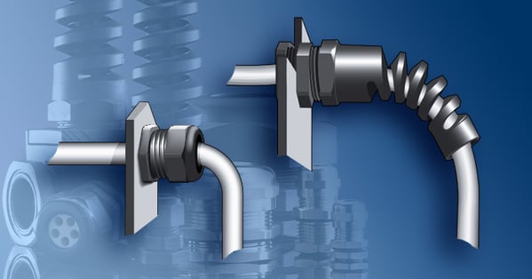
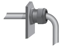
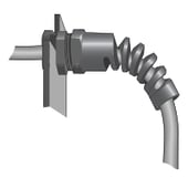
Interpower offers strain reliefs in two general configurations: dome and flex.
| Dome | Flex |
|---|---|
|
Named for its dome shape, this configuration helps secure the wire connection to the equipment. This extends cord life by preventing friction across rough surfaces and sharp edges on the equipment panel. |
This flexible style safely bends the cord entering the equipment. It is designed to eliminate kinking at the point where the cord enters the equipment. The spiral-shaped spring wraps around the cord and adds strength where the cord is most vulnerable. |
 |
 |
Methods of Attachment
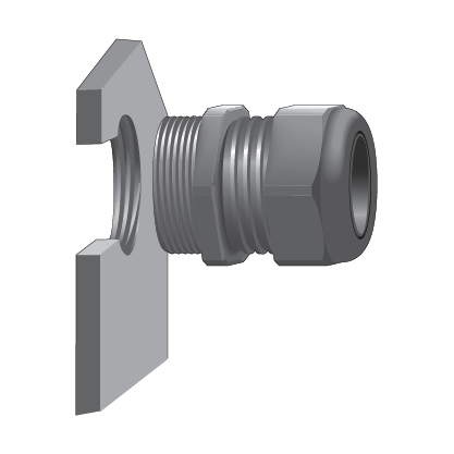
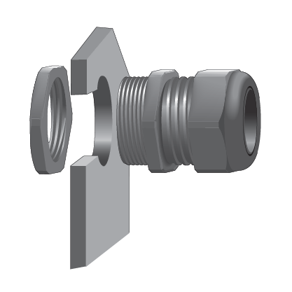
Threaded strain reliefs offered by Interpower are assembled in two different ways. Mounting threads can be threaded directly into the panel of the equipment. Or it can be eased through a clearance hole in the panel of the equipment and fitted with a locking nut. Each option requires a different size clearance hole in the equipment panel. Specifications are found by part number on the Interpower website to assist in determining the correct hole sizing.
| Direct Thread into Panel | Clearance Hole with Nut |
|---|---|
 |
 |
Useful Download

Topics: cable, product design, cable glands, strain reliefs, product development, bend radius